TiLDA MKe
The TiLDA MKe project, Code name "ElectroMagnetic Boogaloo", is being headed by 'RepRap' Matt and Bob
Aim
The main aim of the 2014 badge is to give camp attendees live schedule updates and notifications. As with the original TiLDA we wanted to keep with an Arduino compatible platform that will allow badge hacking during and after the camp. As with previous badge all code and design files are available.
Features and Functions
- Torch mode - Press the light button next to the screen. It will only light up fully if it's hung upside down to avoid blinding
- Snake
- Tetris
- Weather Forecast
- Schedule
- Can receive notifications about upcoming schedule items you're interested in. Visit schedule.emf.camp to set up your account.
Please note that there's a known issue with the badge freezing. We're trying to work out what's causing this, but in the meantime pressing "reset" should get the badge back to life. Help with debugging is highly welcome!
How to get going
Set up your environment
- Plug your badge into your computer via USB
- Download Arduino IDE 1.5.7 from http://arduino.cc/en/main/software#toc3
- “git clone” or download TiLDA source code from https://github.com/emfcamp/Mk2-Firmware
- Start the Arduino IDE.
- Now you have to change the sketchbook-folder to be the folder you just cloned. To do this use File | Preferences | “Set Sketchbook location”. On MacOS, this is Arduino | Preferences
- Restart the Arduino IDE
- Open sketch “EMF2014”
- Set Tools | Board to MKe v0.333 (RTOS Core)
- Set Tools | Port to correct port (you might have to research this - some operating systems like Windows require you to install drivers or become member of a certain group)
- On Macos this is will start /dev/tty.usbmodem with 4 digits, and change for each port
- On Linux this is usually /dev/ttyACM0 but may be a higher number if you have other USB Serial devices
- Hit the upload button
- Wait
- Woohoo - You just successfully uploaded code to your badge
Your first “Hello world” App
There’s a “HelloWorldApp.cpp” file in which you can play around. In order for it to show up on the Homescreen you have to uncomment line 51 in AppManager.cpp and flash the changed code to the badge. Great app pull requests are appreciated!
Why are things so different from standard arduino code?
We’re using a library called FreeRTOS that allows us to multitask - something that’s normally not possible with standard arduino code. This allows us to run multiple tasks at the same time. FreeRTOS uses preemptive scheduling to switch between the task. Due to this we have to be very careful about how we do some things. For example we can’t just define interrupts for buttons in every task (imagine the mess!) or write to the serial port directly (your task might stop in the middle of the message).
We’ve also spend quite a lot of time to make the build-in components as easy to use as possible without having every task to write lots of boilerplate code. If you feel like using the build-in components on the badge, chances are we already wrote a wrapper for them that is already used by one of the other tasks.
Have a look at the “Documentation” section in this document for a full list of API functions. You will avoid a lot of headache if you stick to those.
How to use the badge with pure Arduino code
If you prefer you can always start from scratch without FreeRTOS or any of our code, just keep in mind that you won’t be able to receive messages via radio or use any of the API features we already added. Just start a new sketch in the Arduino IDE for that and get going. If you want to load the main firmware again just change the sketch to “EMF2014” and upload again.
Debugging and Gotchas
- The USB serial is set up to 115220 baud. There are lots of terminals that can connect to them
- If you can’t revive a badge you can short the two erase pins and press the reset button while holding it down.
- Avoid busy waiting, use FreeRTOS queues and Tilda::delay() instead
- Don’t use low level functions like interrupts or serial ports directly unless you really, really know how FreeRTOS will handle them. For general logging you can use Tilda::log()
Code structure
- FreeRTOS has the concept of “Tasks” which work like threads. We’ve wrappered them in a class called “Task” (for background stuff) and “Apps” (for foreground, one-at-a-time things)
- Everything needs to be in the main EMF2014 folder. Subfolders are not allowed. This is an Arduino IDE restriction :(
Radio infrastructure
The radio infrastructure is distributed between DKs. Every “gateway” has a raspberry pi with two ciseco usb radios. We never had the change to actually try it with that many badges in the same spot, so please don’t expect it to work perfectly.
Contribute
Send us pull request via github - We’ll do our best to review and merge the good ones during EMF so others can use them.
Hardware
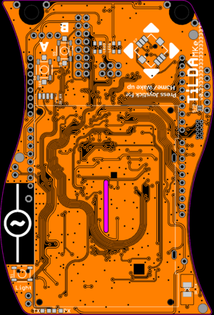
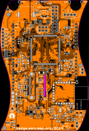
The following hardware has been included on the badge.
- Atmel ATSAM3X8E
- This is the same chip as the Arduino Due and gives us the base platform for the badge
- 32bit ARM Cortex M3 * 84MHz
- 512KBytes Flash RAM
- 96KBytes of SRAM
- A 128x64 pixel monochrome LCD display
- Ciseco SRF Radio
- 868Mhz RF Transceiver
- Simple UART interface
- Low power sleep mode
- MPU-6050 3-axis Accelerometer and 3-axis gyro
- I2C interface
- Tri-Axis angular rate sensor (gyro) with a sensitivity up to 131 LSBs/dps and a full-scale range of ±250, ±500, ±1000, and ±2000dps
- Tri-Axis accelerometer with a programmable full scale range of ±2g, ±4g, ±8g and ±16g
- Digital Motion Processing™ (DMP™) engine offloads complex MotionFusion, sensor timing synchronization and gesture detection
- PMIC & LiPo
- Joystick
- Buttons
- RGB LED's
- IR
- Arduino Headers
- Pads for wearable tech
Firmware Documentation
Debugging
Tilda::log(String text)
This logs “text” to the serial console. To read it connect to it via the Arduino IDE Serial Monitor. Don’t use “SerialUSB.println” or similar -- it’s not thread-safe and you might end up with utter nonsense.
Buttons
The badge has 8 buttons: Up, Down, Left, Right, Center (on the joystick), A, B and Light. You can use arduino-style “digitalRead(BUTTON_RIGHT)” to read the current status of any button, but you can’t define your own interrupt (because we already did that). This doesn’t mean you can’t wait for a certain button to be pressed, it just means you have to approach it slightly differently:
Example: A simple app displaying the button code
void ButtonApp::task() {
    ButtonSubscription allButtons = Tilda::createButtonSubscription(LIGHT | A | B | UP | DOWN | LEFT | RIGHT | CENTER);

    while(true) {
        Button button = allButtons.waitForPress(1000);
        if (button == A) {
            debug::log(“You pressed button A”);
        } else if (button == LEFT) {
            debug::log(“You pressed LEFT”);
        } else if (button == NONE) {
            debug::log(“No button has been pressed in 1000ms”);
        }
    }
}
ButtonSubscription Tilda::createButtonSubscription(<buttons>)
Registers a subscriptions for a defined set of buttons and returns a ButtonSubscription. Multiple Buttons can be combined via “|” (see example above). One button can not be subscribed by more than 10 subscriptions (which shouldn’t really happen, but keep it in mind).
Don’t use this function in a constructor, it requires FreeRTOS to be running. Using it inside the task() function is the only safe place for it.
Button ButtonSubscription::waitForPress(TimeInTicks timeout)
This is normally called in a loop. It causes the task to block until one of the buttons has been pressed. If the timeout occurs before any button has been pressed “NONE” will be returned.
ButtonSubscription::waitForPress()
The same as above, but without the timeout.
ButtonSubscription::clear()
This should be called after an App has been suspended, just before it’s going to be resumed. It causes the Queue to be cleared which could otherwise lead to buttons being reported that have been pressed while other apps were in the foreground. Have a look at the FlashLightApp for an example.
LEDs
Tilda::setLedColor(Led led, Color color);
Tilde::setLedColor(Color color);
Sets the color of all or one led. Color is an object that takes red, green and blue as a value between 0 and 255 each. If no led is defined both leds will be set to the same color.
Example: A simple color-changing task
void ColorfulTask::task() {
    while(true) {
        Tilda::setLedColor(LED1, {255, 0, 0}); // Red
        Tilda::setLedColor(LED2, {0, 255, 0}); // Green
        Tilda::delay(300);
        Tilda::setLedColor(LED1, {0, 255, 0}); // Green
        Tilda::setLedColor(LED2, {0, 0, 255}); // Blue
        Tilda::delay(300);
        Tilda::setLedColor(LED1, {0, 0, 255}); // Blue
        Tilda::setLedColor(LED2, {255, 0, 0}); // Red
        Tilda::delay(300);
    }
}
Display
The Display Library is based on GLCDv3 (http://playground.arduino.cc/Code/GLCDks0108) but adapted to support our screen. The Init routine is called in the setup, and the LCDTask takes care of ensuring the screen is updated every 40ms if required (Unlike the original GLCD library, screen updates are decoupled from the graphics routines.)
Also available is M2tklib (https://code.google.com/p/m2tklib/) which is a nice toolkit library. Further details on using this will come later, but expect the main loop to be handled for you, and just passing the menu structure you require for your app.
Right now, you can call the GLCD functions directly with GLCD.DrawBitmap() for example. This is going to change to be accessed through the GUITask class in the near future, to ensure only one task at a time writes to the screen. Expect this to be simply GUITask in place of GLCD, along with a registering a redraw call back to GUITask.
Extra features that are included, GLCD.SetRotation() will handle rotation of the screen for you, and GLCD.CurrentWidth() and GLCD.CurrentHeight will give you the correct Width and Height for the current orientation. GLCD.Width and GLCD.Height constants are not available, and the GLCD predefined Text areas will not be rotated for you, if you require this define your own text areas.
Sound
There's a piezo on the board, but we haven't added code for it to the current firmware. Pull requests are very welcome!
IMU
Tilda::getOrientation
returns " ORIENTATION_HELD", "ORIENTATION_RIGHT" (joystick to the right of the screen), "ORIENTATION_HUNG" or "ORIENTATION_LEFT"
Flash Storage
We have 2mb of flash storage, but we're not using it in the main firmware - Please get this working!
Data: Schedule
Tilda::getDataStore().getSchedule(day, location)
Date: Weather Forecast
Tilda::getDataStore().getWeatherForecast()
Radio
There's no way of sending messages in the current version of the firmware, sorry :(
Time
Tilda::delay(uint16_t delayInMs)
Works like Arduino’s delay(), but is FreeRTOS-safe. It’s safe to use this function before FreeRTOS has started.
tilda::getClock()
Returns an instance of https://github.com/MarkusLange/Arduino-Due-RTC-Library/blob/master/rtc_clock.h
Settings
uint16_t tilda::getBadgeId()
2.12. Battery
float TiLDA::getBatteryVoltage()
Returns the current voltage as a float
uint8_t TiLDA::getBatteryPercent()
Returns the current voltage as a percentage
uint8_t TiLDA::getChargeState()
Returns the charge state
0 Charging 1 Not Charging
Hacking
To use our board definition you will need to first get the Arduino 1.5.7 IDE from here
Next you can download the TiLDA MKe Firmware project from either the github repo or via direct download
Now copy the "hardware" folder to your Sketchbook folder, this is usually ~/Sketchbook/
or
Alternative option is to set the Arduino 1.5.7 sketchbook folder to the Mk2-Firmware directory.
Start the Arduino IDE and your will be able to select TiLDA MKe v0.333 for the Tools->Board menu
Draft 3d print-able and laser-able case files here
Source
All the source code and designs are on openly available on Github:
- Hardware - the full board design
- Documentation - a dump of relevant parts datasheets
- Firmware - source code for the badge software
- Software - server-side software for the network

