Arduino Workshop for the Curious/Lesson4
Contents |
Communicating with your Computer
Communication with your computer, over the USB cable, can be done by using the Arduino's Serial features. Serial communication needs setting up, to tell it what speed to communicate at. This is done with this line of code:
Serial.begin(9600); // Speed of 9600 bits per second
Then to send messages to your computer you use one of two functions:
Serial.print("Hello "); // This sends the message given to the computer
Serial.println("World!") // Does the same as above, but adds a newline onto the end (so the next message will appear on another line)
Here is a simple hello world program:
void setup() {
  Serial.begin(9600);
  Serial.print("Hello ");
  Serial.println("World!");
}

void loop() {
  // Nothing
}
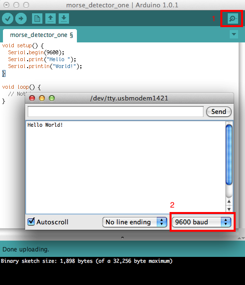
To see the text being sent from your Arduino to your computer press the Serial Monitor button in the Arduino software (shown as 1 in the image below). Make sure your computer's serial speed is set correctly (shown as 2 in the image below).
|
(1) In the loop, use serial to print the numbers 1 to 10 to your computer. |
Making a Sensor
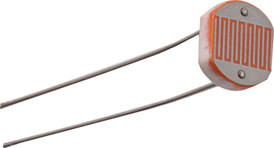
The sensor is based upon a light dependent resistor, which (as the name suggests) changes its electrical resistance with the amount of light hitting it. They look like this:

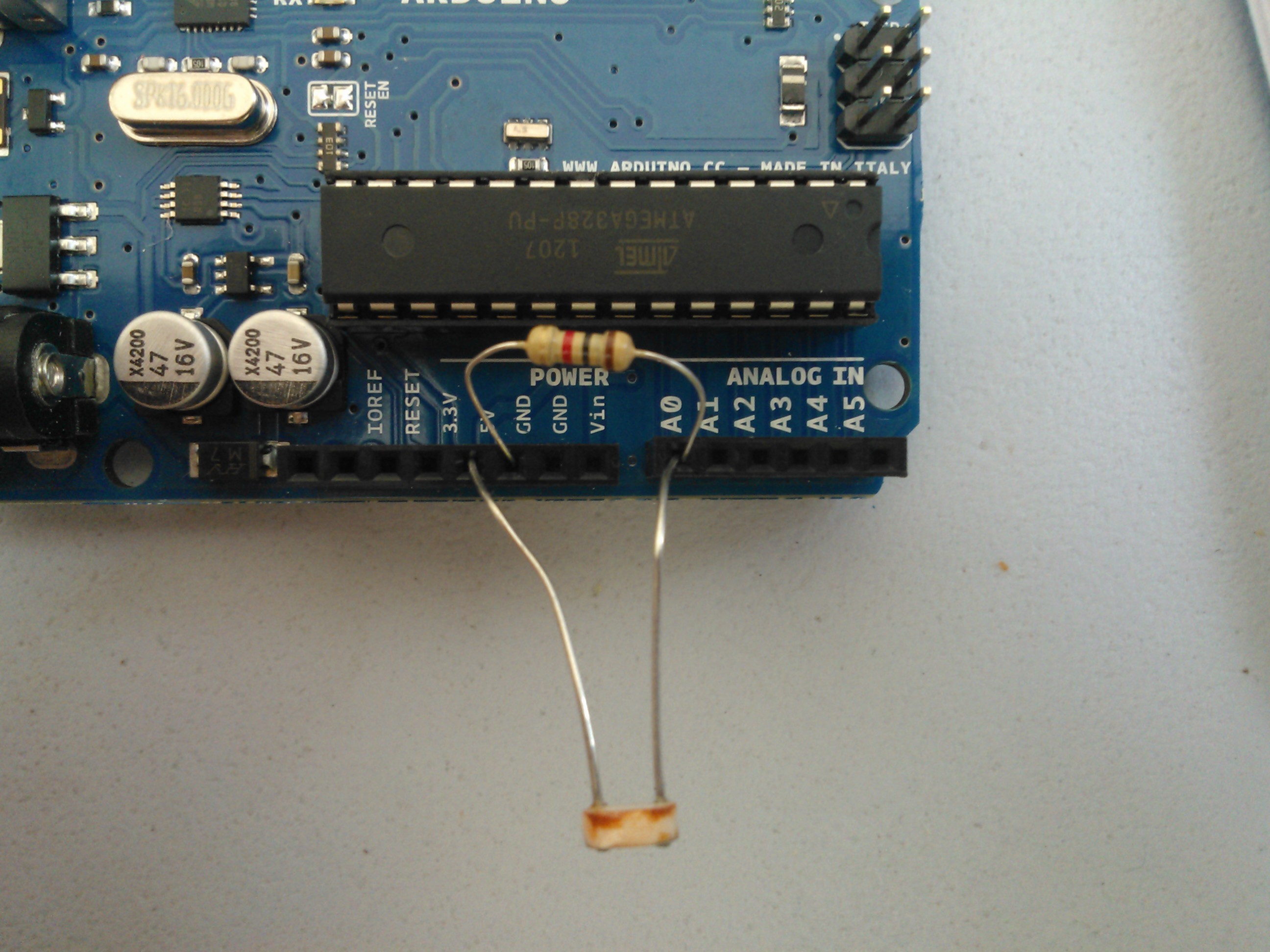
A potential divider circuit is used to convert the light sensor's varying resistance into a varying voltage. If you don't know what this is, please check out this explanation. Here are two photos of the potential divider set up, one using the breadboard, and one without it.
Reading Analog Signals
Analog signals can be read from 6 inputs (labelled A0 to A5). We have plugged the sensor into pin A0, so to read the signal we do this:
int reading = analogRead(0);
The reading variable will then contain a number between 0 and 1023, where 0 represents 0V, 1023 represents 5V. A value of 512 therefore represents 2.5V.
|
(1) Print analog readings over the serial port to your computer. (Make sure you have a delay between measurements!) (2) Convert the reading to a voltage using maths and print that over serial instead. (3) Instead of the reading value, print a bar of # symbols who's length is proportional to the voltage reading |
Detecting Dots and Dashes
When the light from an LED hits your LDR you should receive a high voltage reading. It should be a low voltage reading when there is no light landing on your LDR. Have a friend program their Arduino to send the "SOS" morse code using their LED, point that at your LDR and record the max and min analog readings you get (corresponding to the LED being on and off respectively). Then paste this function into your Arduino code:
int threshold = 512;

boolean isLedOn() {
  int reading = analogRead(0);
  if(reading < threshold) {
    return false;
  } else {
    return true;
  }
}
This function returns true if your reading was above the threshold, and false if it was below. Copy the whole code below and change the threshold value to be between your min and max readings.
void setup() {
  Serial.begin(9600);
}

void loop() {
  if(ledIsOn()) {
    Serial.println("#");
  } else {
    Serial.println("-");
  }
  delay(100);
}

int threshold = CHANGE_TO_THRESHOLD;

boolean ledIsOn() {
  int reading = analogRead(0);
  if(reading < threshold) {
    return false;
  } else {
    return true;
  }
}


